
Manually Set Beamcenter Window#
The Manually set beamcenter window allows to select the beamcenter in detector pixel coordinates, either by setting the pixel position directly or by using a graphical interface. The functionality is limited in the sense that a perfect detector orientation is assumed (i.e. all rotations are zero) and it is not possible to optimize rotations. If that is required, please perform a full calibration.
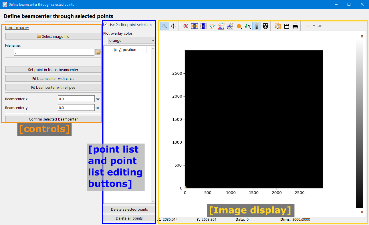
The left side offers controls, the central panel is a list to view and edit points selected in an image and am image plot is shown on the right.
Image display#
The image display is a PydidasPlot2d with all the functionality described in the linked description. In addition, clicking with the left mouse buttons allows to store the selected positions. Points are visualized by different symbols, as explained below.
point symbol |
description |
|---|---|

|
A generic x marker to signal that this point has been stored. |

|
Selected points are highlighted with a filled circle. |

|
The beamcenter is marker with a diamond-shaped marker. |
Point list and controls#
Located at the top are controls for how to select points and for the overlay color.
Use 2 click point selection toggles how points are selected in the image:
Disabled 2-click point selection:
If disabled, points will be selected directly with a single click in the image. This requires the user to manually zoom in to select points with high accuracy.
Enabled 2-click point selection:
When enabled, clicking on a point in the image will zoom in on the selected point to allow a higher degree of precision for the point selection. The second click will select the point and reset the zoom to the previous settings.
The second item is a configuration widget to change the color of all the plot overlay items like the points to increase the contrast, depending on the chosen colormap for the image. Changing the color in the drop-down selection will automatically update the color in all overlay items.
The point list displays the positions of all clicked points. Left-clicking on a
point in the list will select this point and also highlight it in the image by
changing the marker. Multiple points can be selected by holding Shift
when selecting the second point to select all points inbetween or by holding
Ctrl while selecting points to add only single points to the
selection. All selected points will be highlighted in the image.
The two buttons at the bottom of the point list allow to delete the current
selection of points or all points. The current selection of points can also be
deleted by pressing Del while the plot list has the focus.
Controls#
File input#
The input file can be selected in any one of four ways:
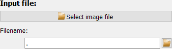
Use the “Select image file” button at the top.
Enter the full file path in the input field.
Use the small “open” button right of the input field.
Drag and drop a file from the system’s file explorer.
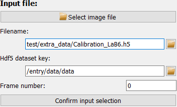
If the filename is valid, the selected file will be displayed immediately.
For hdf5 files, however, you need to select data the dataset and frame number first and confirm the selection with the “Confirm input selection” button before any frame is loaded and displayed.
After loading an image, the current integration region is shown as an overlay. By default,the overlay is orange and will cover the full image (because the full detector is used by default).
Beamcenter selection#
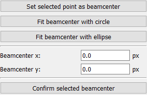
The beamcenter position (in detector pixel coordinates) can be set directly, if it is known.
The following control buttons are availabe:
Set selected point as beamcenter: This button requires to have marked exactly one point in the image. Clicking this button will take that point’s coordinates as the new beamcenter. Note that the list of points must have exactly one entry, not one selected entry.
Fit beamcenter with circle: All points in the list will be used as coordinates to fit a circle. The center will be taken as new beamcenter and the fitted circle will be shown as overlay in the image.
Fit beamcenter with ellipse: Similar to the button above, but an ellipse instead of a circle is used to find the beamcenter. Fitting an ellipse requires selecting at least 5 points on the circumference.
The last button at the bottom, Confirm selected beamcenter, will
close the window and convert the selected beamcenter to pyFAI PONI coordinates
and update the DiffractionExperiment.